Blinkenlights Pi Powered Light Switch
What do you do when you don’t feel like getting up from your desk to turn on the lights? Build a better light switch! This project involves using a Raspberry Pi Zero to toggle both circuits of a two-gang light switch. The Pi does this by driving a mechanical relay switch rated for high AC voltage, that does the actual switching.
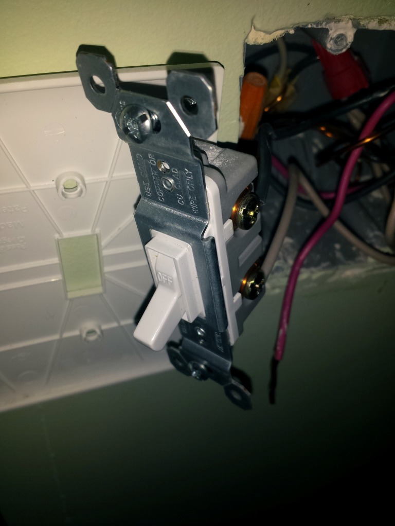
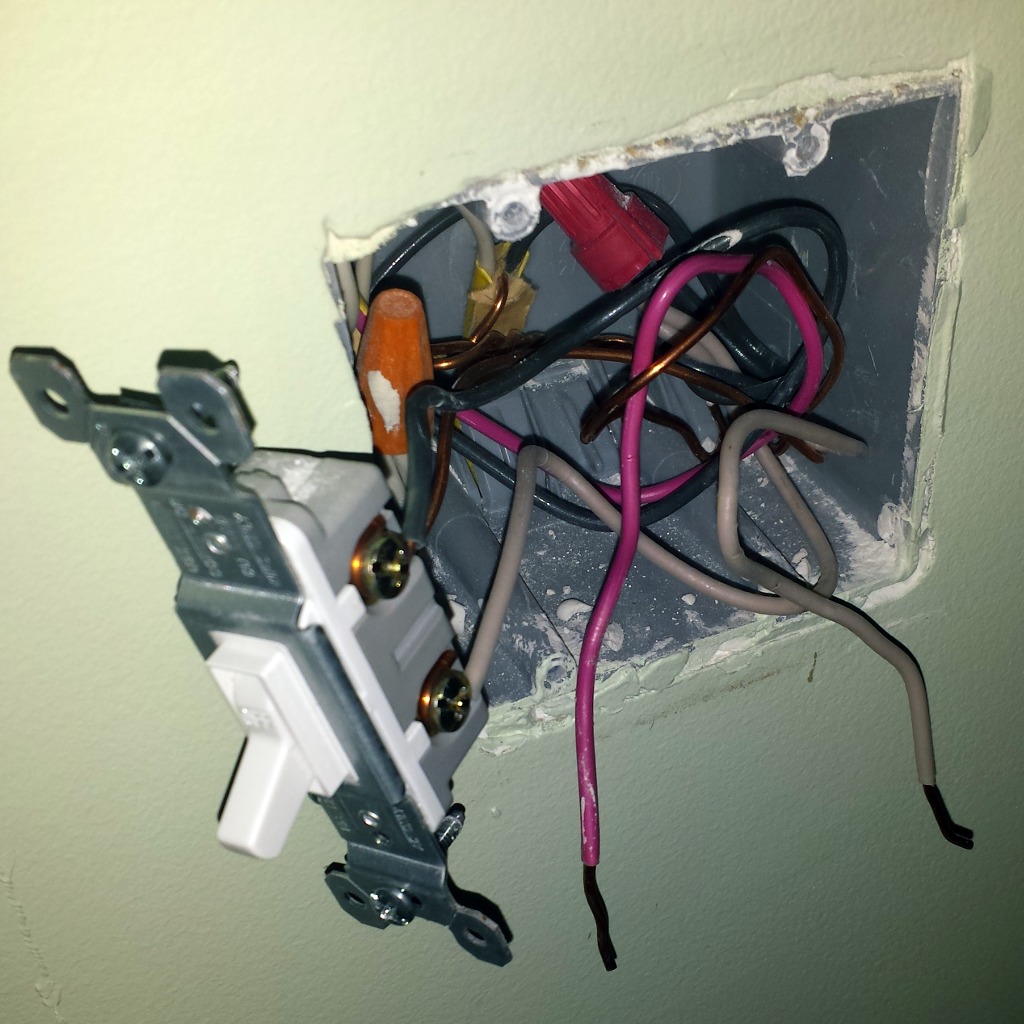
I started by removing the face plate from the light switch box to get a feel for how the new switch will need to work. Before taking the plate off of any electrical box, make sure to switch the mains power off. While this doesn’t give the best lighting for pictures, it does prevent accidental electrical shocks. While I was in there, I took measurements for the new switch plate, and practiced removing one of the switches.
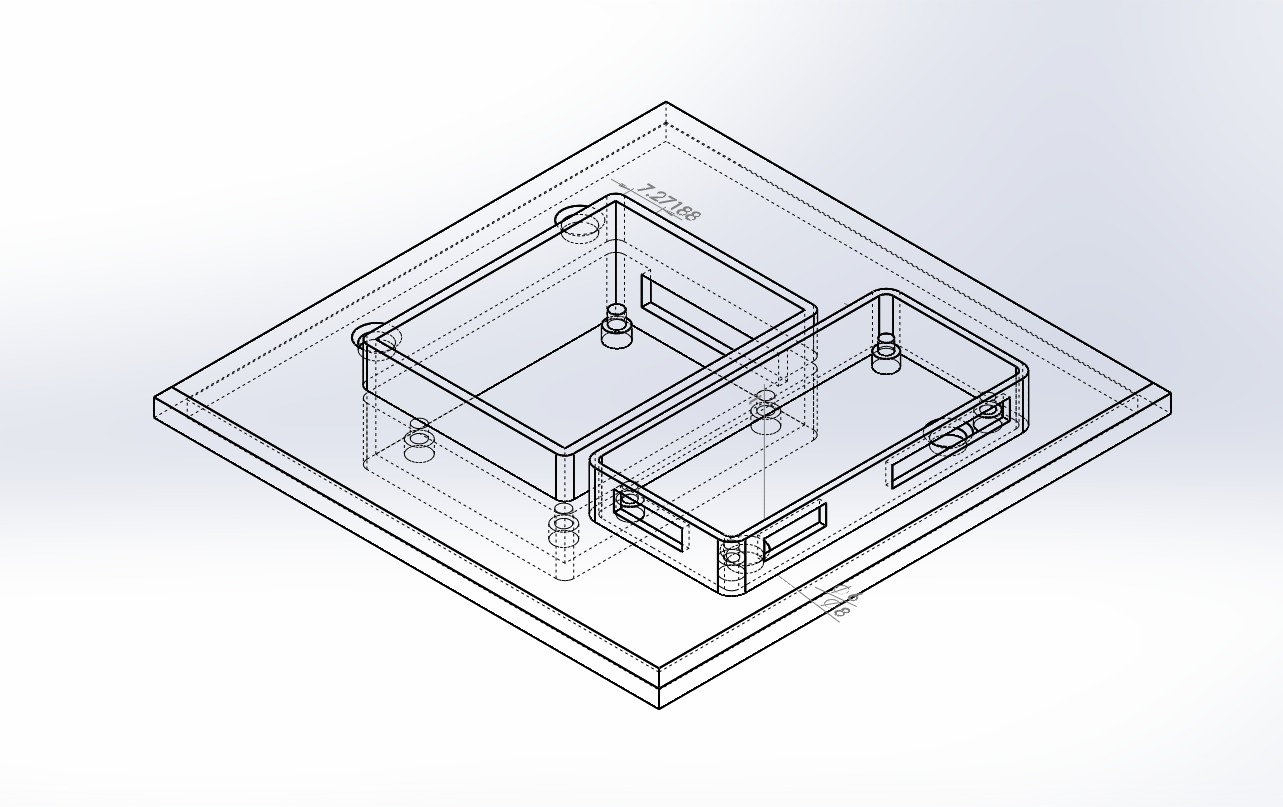
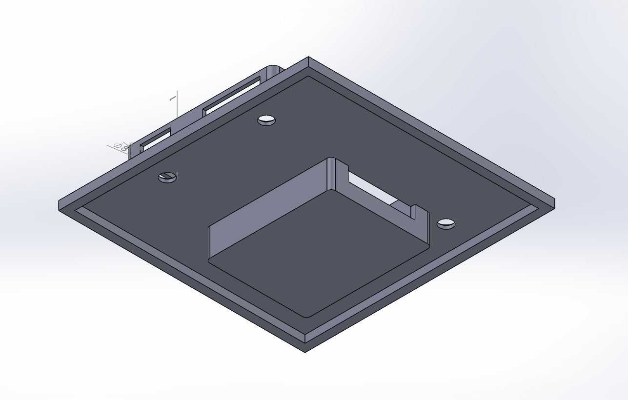
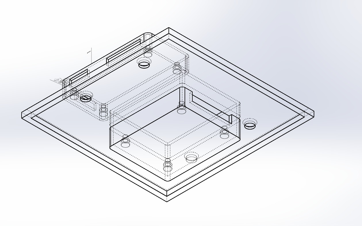
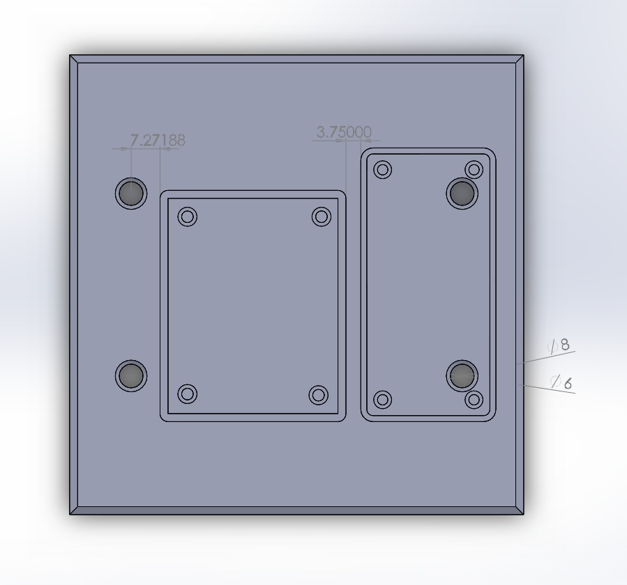
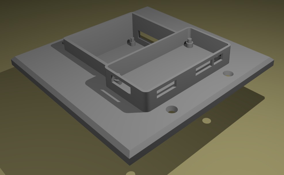
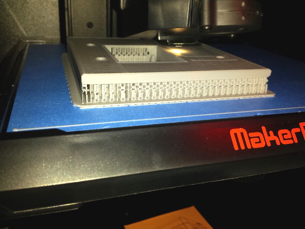
Using the dimensions taken from the existing switch plate and box, and from the Raspberry Pi and relay hardware, I modeled the new switch plate in SolidWorks. Many of the dimensions used for the Pi enclosure side were taken from Adafruit’s wonderful Pi Zero Case, available on Thingiverse. From there, it was exported to an STL file, which was imported into Blender for a 3D render, and into MakerBot Desktop for slicing. After slicing, it was printed on a MakerBot Replicator 3D printer.
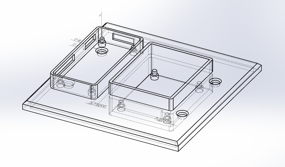
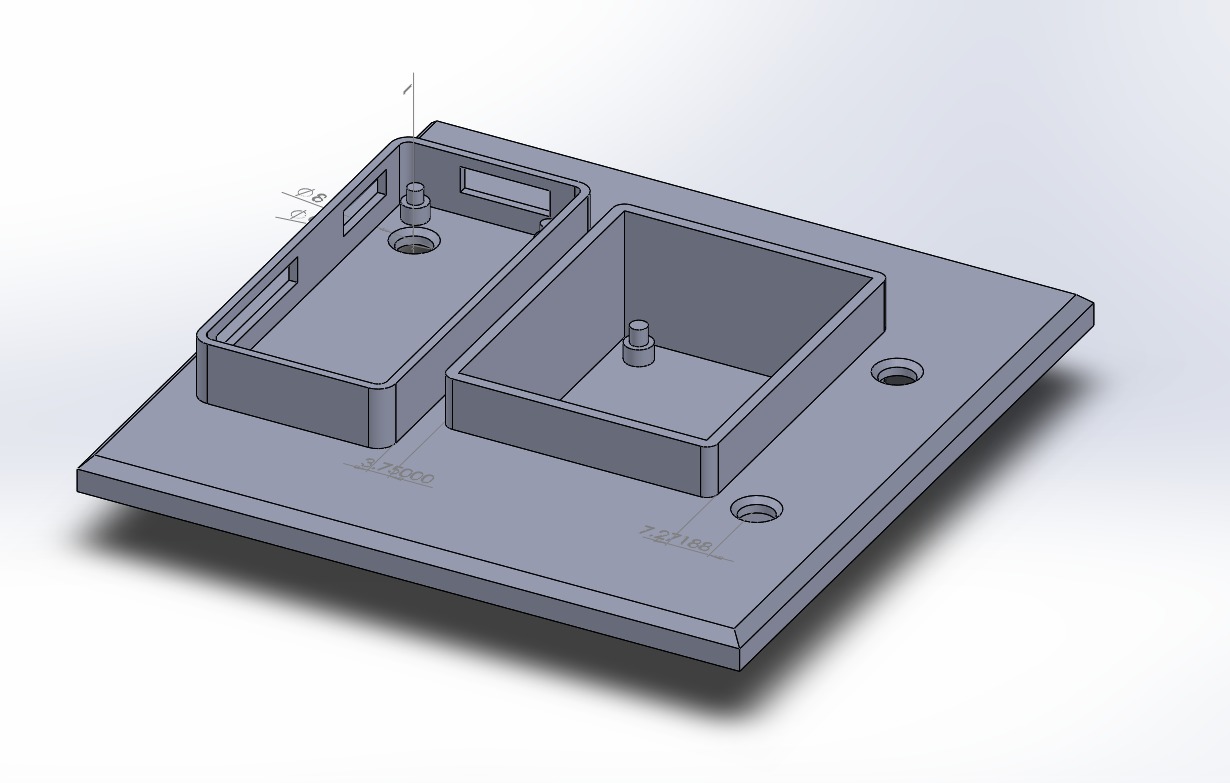
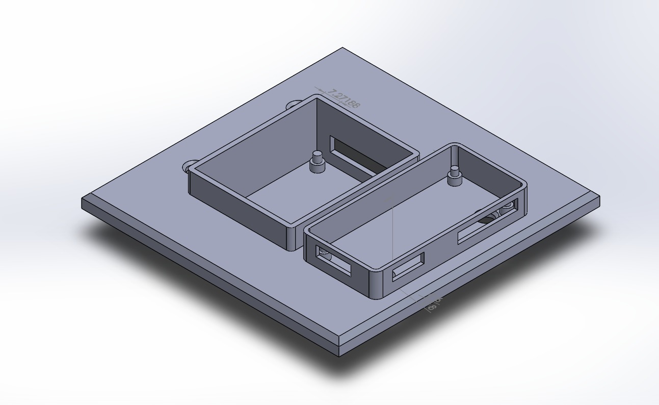
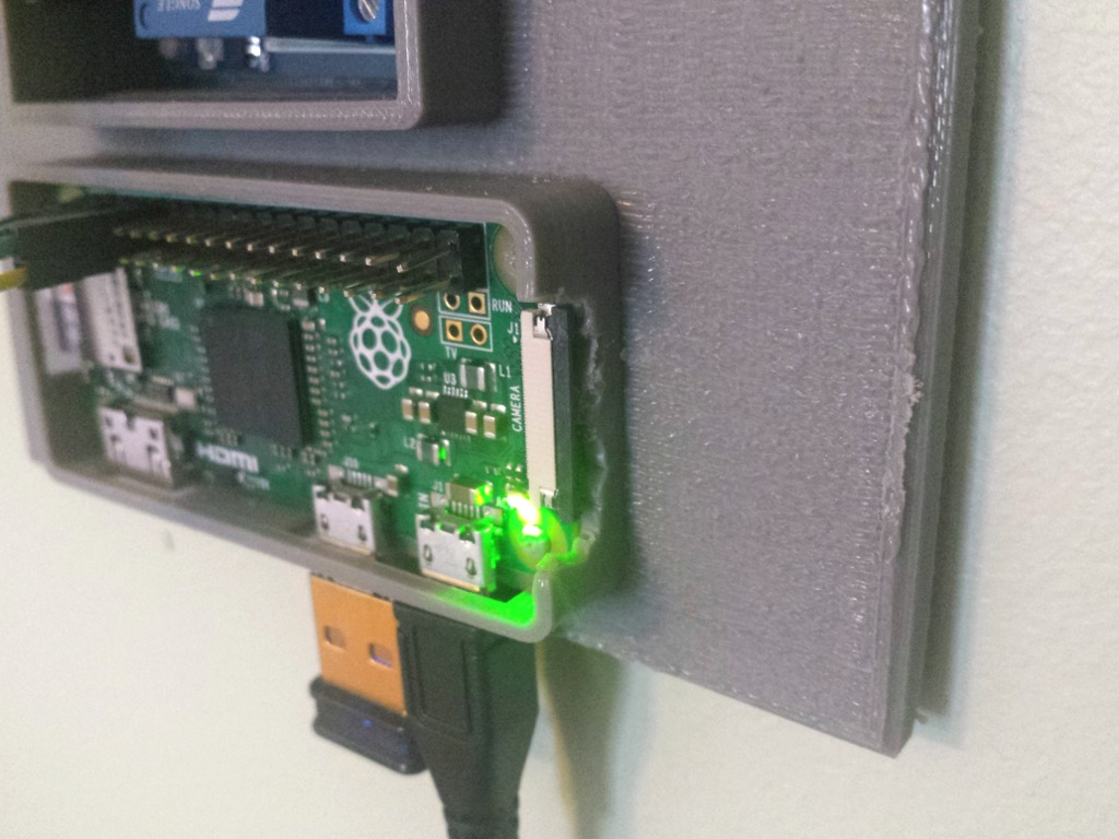
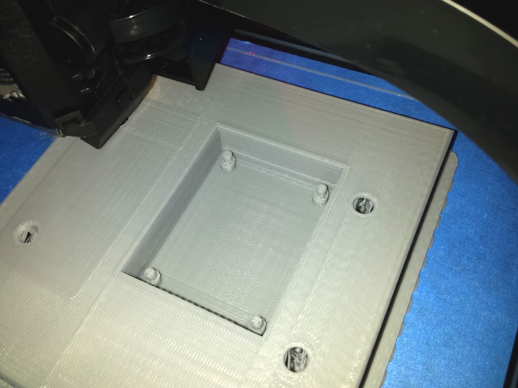
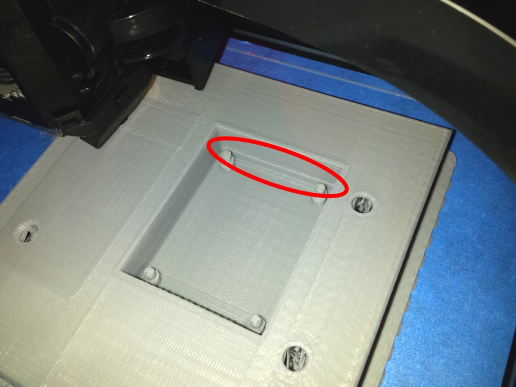
During the print, there was some slight shifting along the horizontal plane, resulting in a distinct break between the bottom of the relay housing and the rest of the plate. This was fixed using a lighter and a paper clip to heat weld the plastic back together. Also, the measurements taken from the Adafruit case did not include space for the new camera connector, which proved to be an issue later on. I ended up cutting a space out of the printed part with a heated razor blade, which can be seen later in the photos of the mounted switch plate.
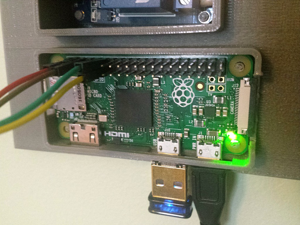
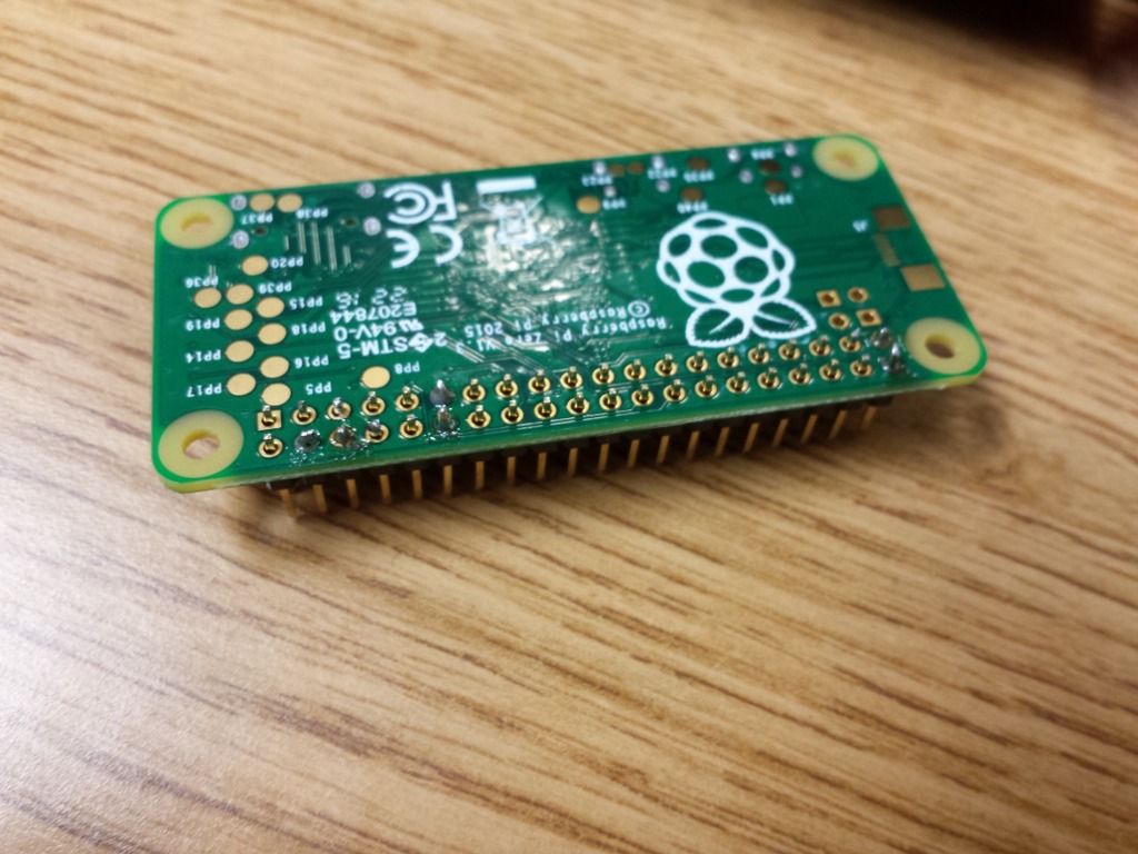
It’s time to begin assembling the electronics. I ordered a starter kit from Adafruit that included, among other things, a Pi Zero and a solderable 2x20 male pin header. While holding contacts together by hand can work in a pinch, soldering the header on would allow me to much more easily connect components using standard breadboard jumper cables. Because the pins are so small, and this was my frst time soldering, I opted to only solder the pins I was going to use. Thankfully, there’s a helpful guide to the raspberry pi pinout at https://pinout.xyz/. I chose to solder pins 4 (5v), 6 (GND), 11 (GPIO 17), 12 (GPIO 18), and 39 (GND). I won’t be using pin 39 electrically, but I chose it to help adhere the other end of the header to the board.
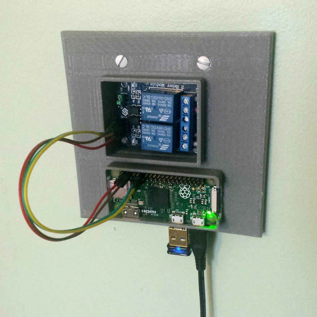
For the relay circuit, I picked this two channel relay, rated up to 250ACV/10A. It connects to the Pi very simply, just connect the VCC pin on the relay to a 5v pin on the Pi, the GND pin on the relay to the GND pin on the Pi, and the IN1 and IN2 pins on the relay to two switchable GPIO pins on the Pi. The mains wires connect fairly simply as well, with the connection to be switched being inserted into the center screw terminal for each channel.
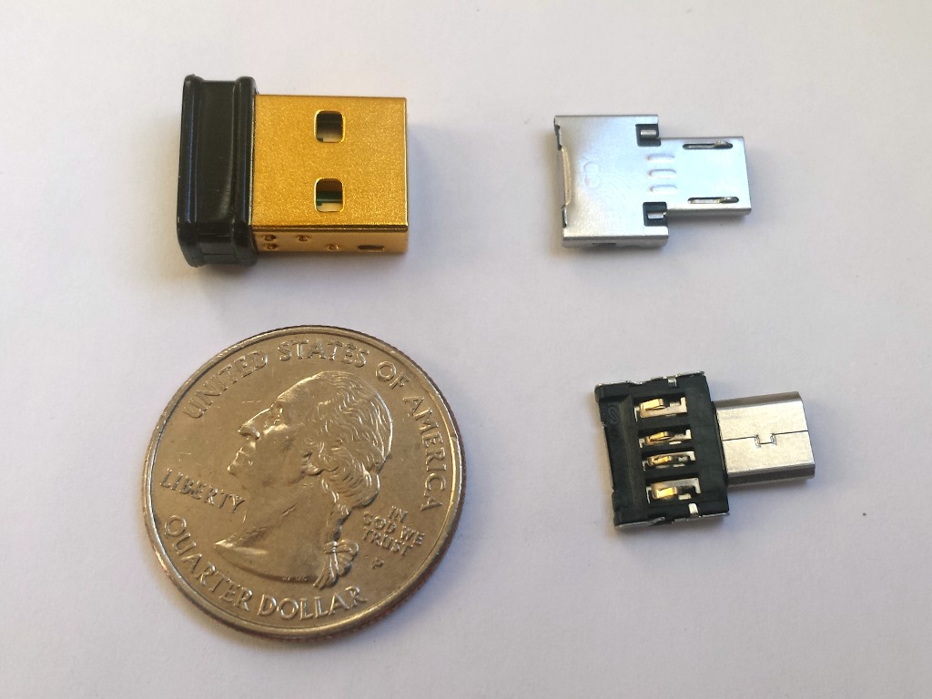
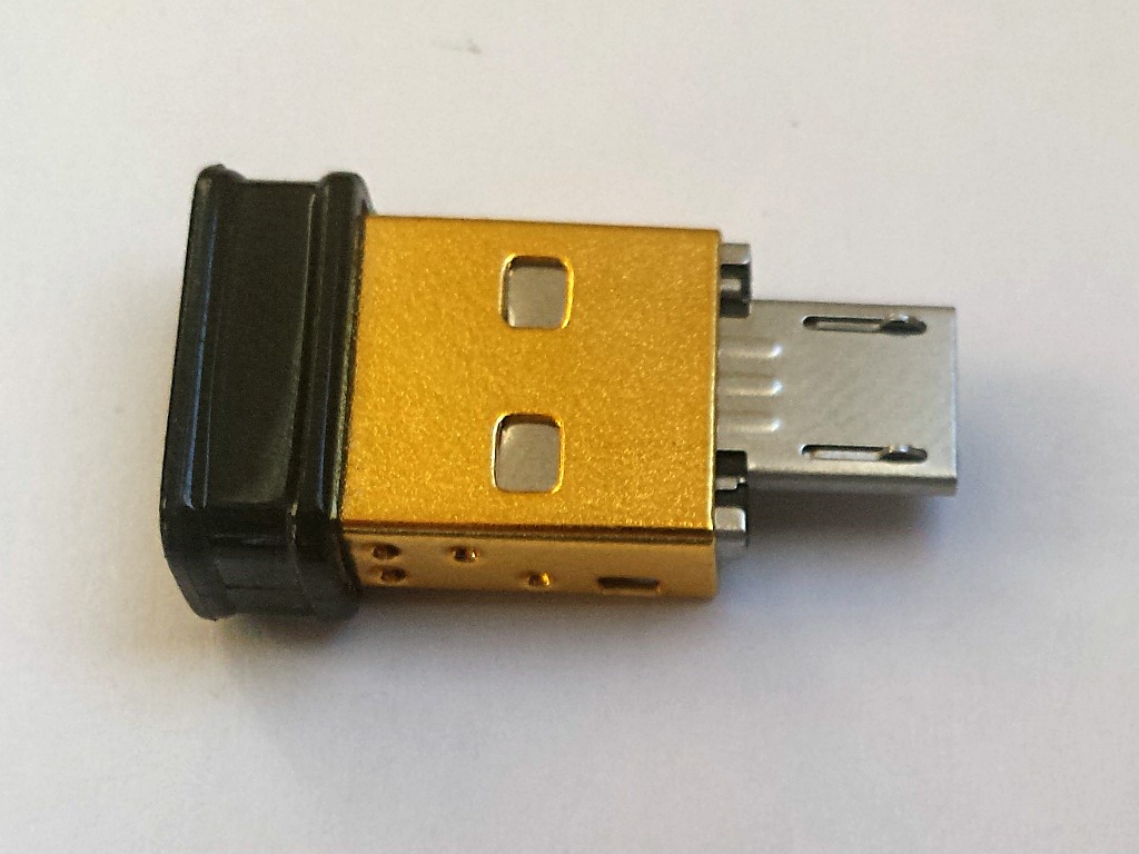
Another necessary peripheral is the wireless adapter. I’ve used the Edimax EW-7811Un with many of devices in the past, and its small footprint makes it ideal for the Raspberry Pi. The plastic casing of the adapter is somewhat fragile and usually breaks off in a few months of normal use on a laptop, but this won’t be an issue here since the Pi will be stationary. Unfortunately, the Pi Zero only has MicroUSB ports, meaning the wifi connector cannot be connected directly. To remedy this issue, I am using a small form factor USB to MicroUSB adapter that slots inside of the much larger USB connector.
Mounted on the wall, I couldn’t get it to work. The ground pins I tried to solder earlier were not making a good electrical connection. As a temporary fix, I pushed the ground wire into the Pi’s composite through-hole ground connection.